Warhead Verification with Electric Cryptography
Contact: Areg Danagoulian (aregjan@mit.edu)
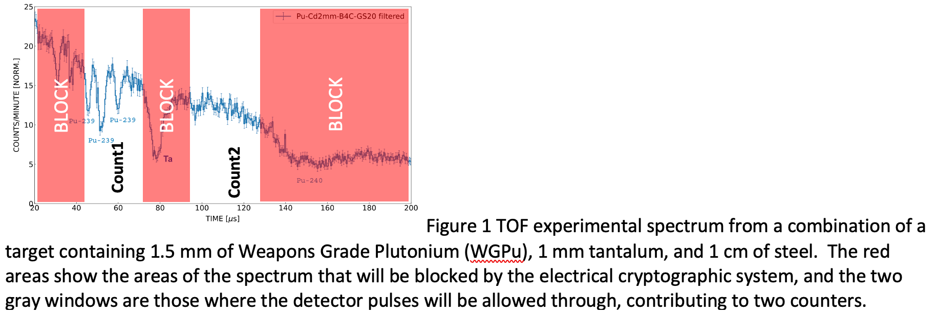
Warhead verification needs to achieve the three goals of a Zero Knowledge Proof (ZKP): sensitivity to a hoax; specificity; privacy. Research efforts by MIT have shown that epithermal neutron beams can be used in time-of-flight (TOF) mode to achieve these three goals[1] in a physically cryptographic manner. Furthermore, efforts by MIT and Princeton[2], as well as more recent collaborative efforts between PNNL and MIT have shown that compact, DT-generator based beams can be used to differentiate between various fissile isotopes. We want to go one step further and achieve ZKP by abandoning the digital realm and instead using a system consisting of a limited number (40-100) of analog electrical components, such as ~cm scale resistors, capacitors, and bipolar junction transistors. Such a system will filter out the TOF signal and produce just simple counts in particular energy windows. These counts then can be used to perform verification, without revealing any additional information. See Figure 1 as an illustration.
Electricity
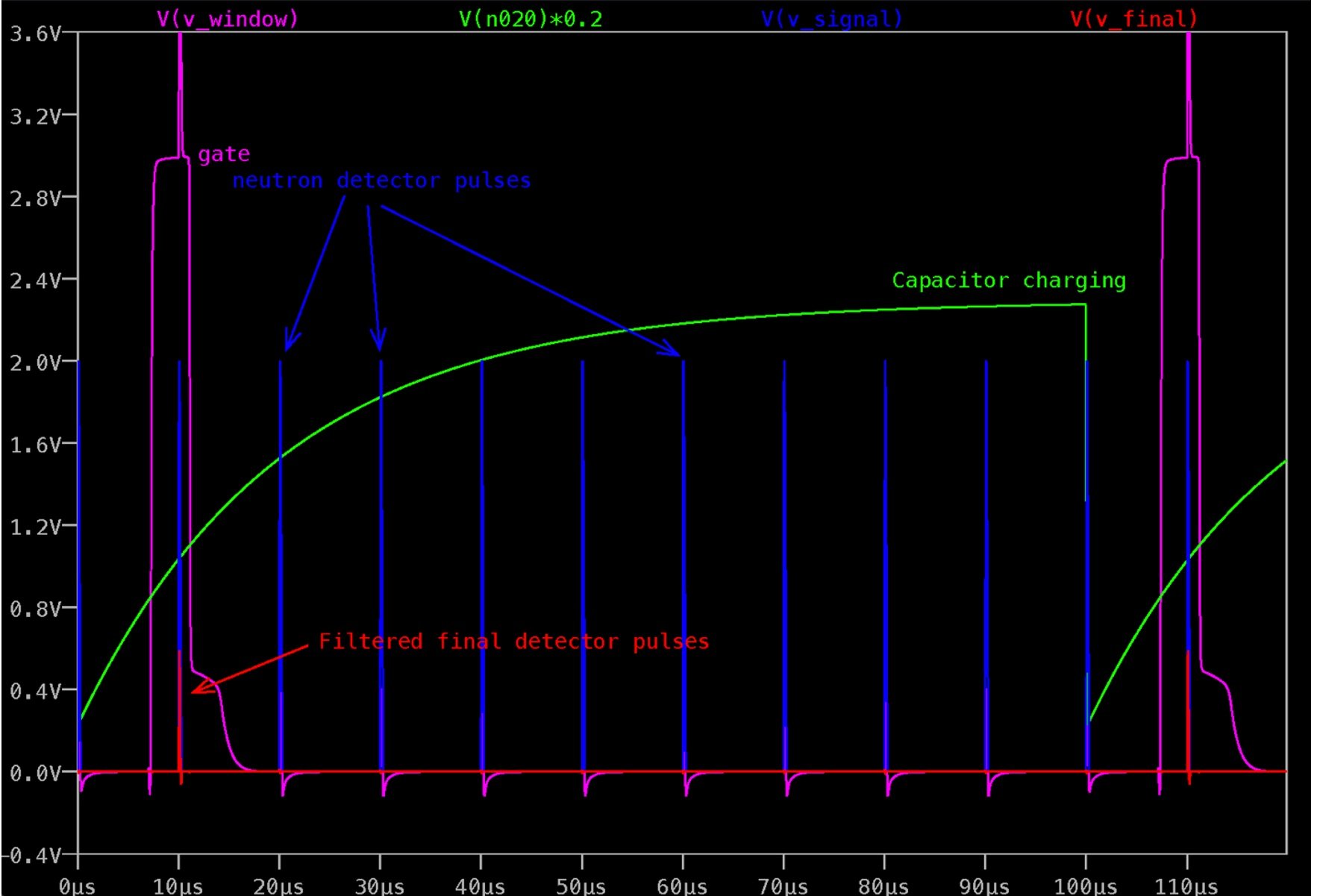
But how does one apply the time delays described in Figure 1? The simplest way of achieving this, using analog devices, is to switch from time domain to voltage domain using a simple charging capacitor in RC configuration. See Figure 3 for the circuit layout of the proposed system. Here the DT generates the t0, which starts the charging of the capacitor. Preliminary circuit design has been performed -- the circuit has been simulated in LTspice as well as breadboard-level circuitry. Figure 5 shows the full circuit design. Figure 2 shows the evolution of the detector signal, as it passes through the filtering gate. The filtered signal (red) shows suppression of all pulses which do not fall into the gate. This filtered signal can then be used to either trigger a mechanical analog counter, or be fed into an analog-circuit based ripple counter.
Figure 2 Filtering of the detector signal (blue). Red is the final filtered signal, showing suppression of all pulses that are outside of the gate (magenta) produced by the comparators triggering on the charging capacitor (green).
Figure 3 The full circuit design in LTSpice, showing the TTL input from the DT generator, the charging capacitor, the layout of the two comparators defining the filtering gate, and the final gating circuitry which filters the detector signal.
Necessary skills:
· Good understanding of (analog) circuit design
· Proficiency in Spice, LTSpice, or similar
· Willingness to learn about nuclear detection and arms control
[1] See Engel and Danagoulian, https://www.nature.com/articles/s41467-019-12386-0
[2] See Klein et al., https://doi.org/10.1103/PhysRevApplied.15.054026